Moving Coil Meter
Inside a meter (Fig 1), with a tight coil of copper wire, wrapped round a soft iron core, is mounted in between the poles of a permanent magnet. The coil has connections at either end so you can pass an electric current through it and it has a long pointer stuck to it that runs out across the meter dial. When you connect the meter into a circuit and turn on the current, the current creates a magnetic field in the coil. The field repels the magnetic field created by the permanent magnet, making the coil rotate and turning the pointer up the scale. The more current that flows through the coil, the bigger the magnetic field it creates, the greater the repulsion, the more the coil turns, and the further up the scale the pointer goes. So the pointer gives you a measurement of how much current is passing through the coil. With appropriate calibration, you can use the dial to measure the current directly.
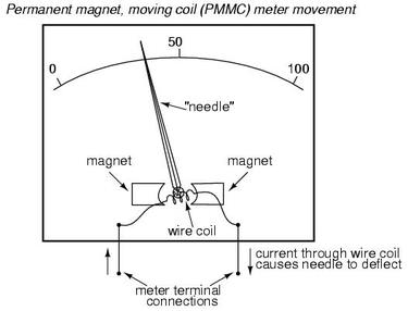
Fig 1. Moving Coil Instrument
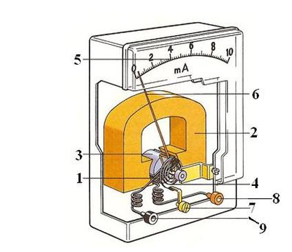
Fig 2. Moving Coil Instrument showing internal connections.
Fig 2 shows a rectangular coil (1) wrapped on a soft iron aluminum core mounted so that it can rotate between the poles of a permanent magnet (2). A soft iron core (3) ensures that a uniform magnetic field acts on the coil. When a current flows in the coil it experiences a torque/force which tries to turn it against the tension in a hair spring (4). The extent to which the coil turns depends on the current flowing and this is read off on a scale (5) with the aid of a pointer (6) attached to the coil assembly. Adjustment screw (7) is provided for zeroing the pointer and the instrument is connected into a circuit through terminals/leads (8) and (9).
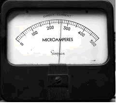
Fig 3. Linear Scale meter
Scale – The scale for this meter is linear (evenly spaced).
Advantages and Disadvantages
Advantages
1. Very Accurate
2. Even Scale
3. Unaffected by stray magnetic fields.
Disadvantages
1. Expensive
2. Unsuitable for a.c
3. Easily damaged.
Advantages and Disadvantages
Advantages
1. Very Accurate
2. Even Scale
3. Unaffected by stray magnetic fields.
Disadvantages
1. Expensive
2. Unsuitable for a.c
3. Easily damaged.
Moving-Iron Instrument
This can be used to measure a.c. or d.c. Its movement will depend upon the attraction or repulsion force between a fixed and a moving iron. The fixed iron is joined to the framework on which the instrument coil is wound, while the moving iron is joined to one end of the pointer.
NOTE: Both irons in a moving-iron instrument are magnetised in the same direction regardless of the current direction in the coil, and repulsion between the two irons always occurs to move the pointer.
NOTE: Both irons in a moving-iron instrument are magnetised in the same direction regardless of the current direction in the coil, and repulsion between the two irons always occurs to move the pointer.
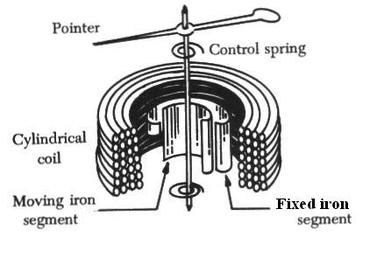
Fig 4. Moving Iron instrument
Fig 5. Uneven Scale meter.
Scale – The scale for this meter is non-linear (unevenly spaced).
Advantages and Disadvantages
Advantages
1. Cheap
2. Strong and Tough
3. Can be used on a.c to d.c
Disadvantages
1. Uneven and cramped scale
2. Affected by temperature changes and stray magnetic fields.
Applications. Used on industrial panels, especially where vibration is considerable, and motor starters.
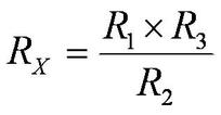
Wheatstone bridge.
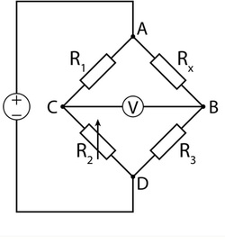
Fig 6. The Wheatstone Bridge
This is an electrical circuit used to measure an unknown electrical resistance by balancing two legs of a bridge circuit, one leg of which includes the unknown component. Its operation is similar to the original potentiometer.
In the figure, Rx is the unknown resistance to be measured; R1 , R2 and R3 are resistors of known resistance and the resistance of R2 is adjustable. If the ratio of the two resistances in the known leg (R2/R1) is equal to the ratio of the two in the unknown leg (R3/Rx), then the voltage between the two midpoints (B and C) will be zero and no current will flow through the galvanometer V. If the bridge is unbalanced, the direction of the current indicates whether R2 is too high or too low. R2 is varied until there is no current through the galvanometer, which then reads zero.
Applications (Practical uses) of the Wheatstone bridge
1. http://www.wisc-online.com/objects/ViewObject.aspx?ID=DCE4403
At the point of balance/zero;