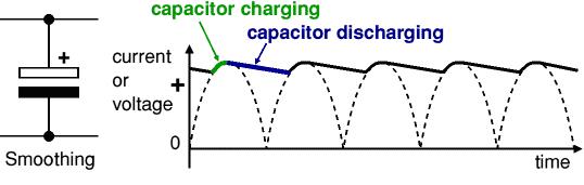
Smoothing
Smoothing – to minimise the output ripple across the load. Smoothing is performed by a large value electrolytic capacitor connected across the DC supply to act as a reservoir, supplying current to the output when the varying DC voltage from the rectifier is falling. The diagram shows the unsmoothed varying DC (dotted line) and the smoothed DC (solid line). The capacitor charges quickly near the peak of the varying DC, and then discharges as it supplies current to the output.
Note that smoothing significantly increases the average DC voltage to almost the peak value (1.4 × RMS value). For example 6V RMS AC is rectified to full wave DC of about 4.6V RMS (1.4V is lost in the bridge rectifier), with smoothing this increases to almost the peak value giving 1.4 × 4.6 = 6.4V smooth DC.
Smoothing is not perfect due to the capacitor voltage falling a little as it discharges, giving a small ripple voltage. For many circuits a ripple which is 10% of the supply voltage is satisfactory and the equation below gives the required value for the smoothing capacitor. A larger capacitor will give less ripple. The capacitor value must be doubled when smoothing half-wave DC.
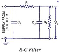
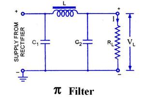
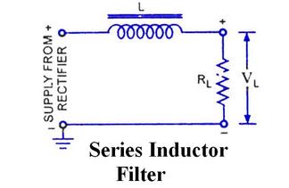
Filter Circuits
Smoothing is not perfect due to the capacitor voltage falling a little as it discharges, giving a small ripple voltage. For many circuits a ripple which is 10% of the supply voltage is satisfactory and the equation below gives the required value for the smoothing capacitor. A larger capacitor will give less ripple. The capacitor value must be doubled when smoothing half-wave DC.
Filter Circuits
Regulator
This is a device that maintains the terminal voltage of a generator or other voltage source (within required limits) despite variations in input voltage or load.
Voltage regulator ICs are available with fixed (typically 5, 12 and 15V) or variable output voltages. They are also rated by the maximum current they can pass. Negative voltage regulators are available, mainly for use in dual supplies.
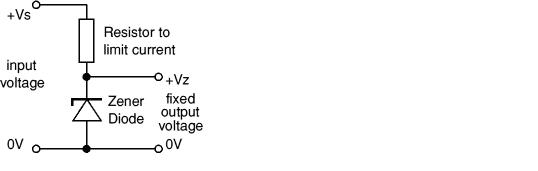
Zener Diode Regulator
For low current power supplies a simple voltage regulator can be made with a resistor and a zener diode connected in reverse as shown in the diagram.Zener diodes are rated by their breakdown voltage Vz and maximum power Pz (typically 400mW or 1.3W). The resistor limits the current. The current through the resistor is constant, so when there is no output current all the current flows through the zener diode and its power rating Pz must be large enough to withstand this.
This is a device that maintains the terminal voltage of a generator or other voltage source (within required limits) despite variations in input voltage or load.
Voltage regulator ICs are available with fixed (typically 5, 12 and 15V) or variable output voltages. They are also rated by the maximum current they can pass. Negative voltage regulators are available, mainly for use in dual supplies.
Zener Diode Regulator
For low current power supplies a simple voltage regulator can be made with a resistor and a zener diode connected in reverse as shown in the diagram.Zener diodes are rated by their breakdown voltage Vz and maximum power Pz (typically 400mW or 1.3W). The resistor limits the current. The current through the resistor is constant, so when there is no output current all the current flows through the zener diode and its power rating Pz must be large enough to withstand this.